In part 1 I discussed the basics of putting a battery together. In this installment I’ll be talking more in depth about the cells and BMS as well as other things like the tools you need to build your system.
BMS selection – there are a number of BMS (Battery Management System) options on the market. There is JK, JBD, Daly and many others. In my extensive testing JK seems to always be the best in terms of features and the cost is always in line with the others. JK makes 3 different lines of BMSes that are of use in solar systems. The B series, B2 series and PB series.
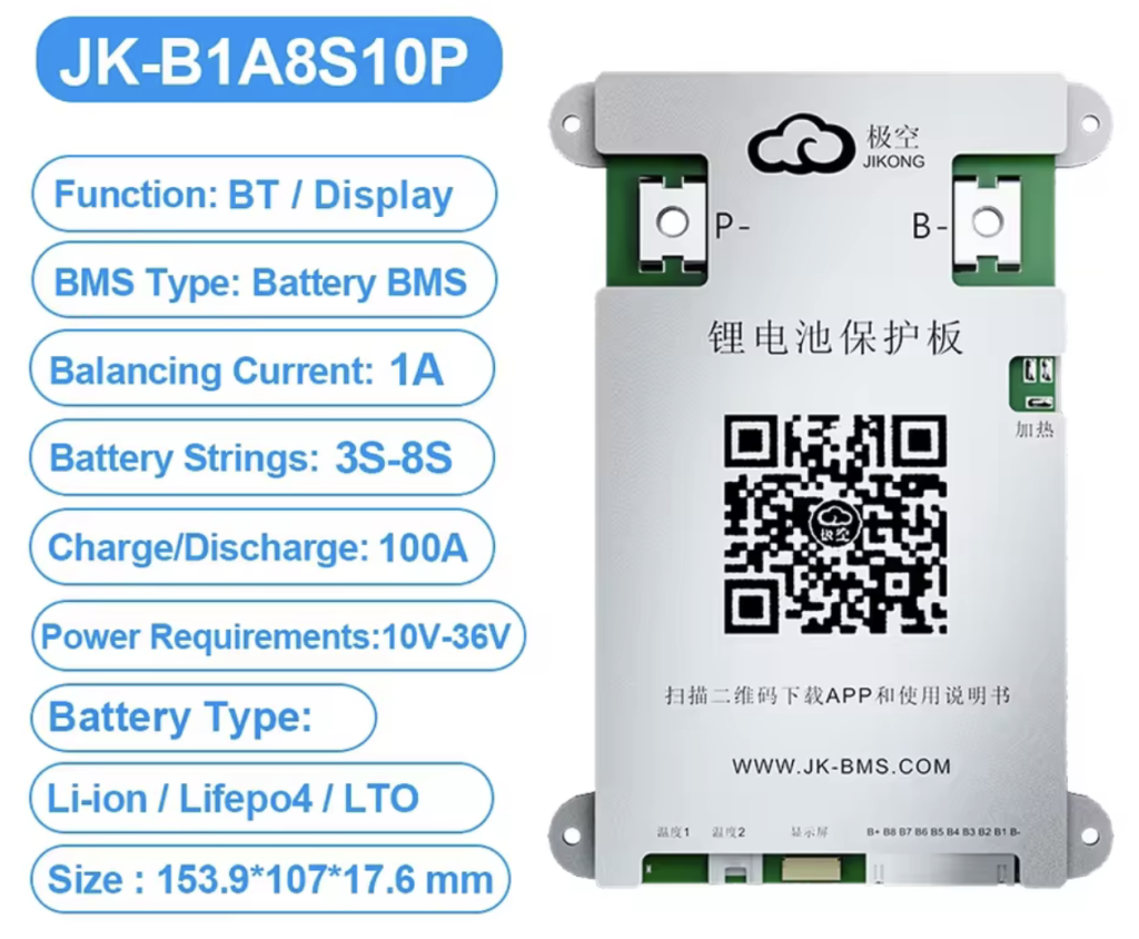
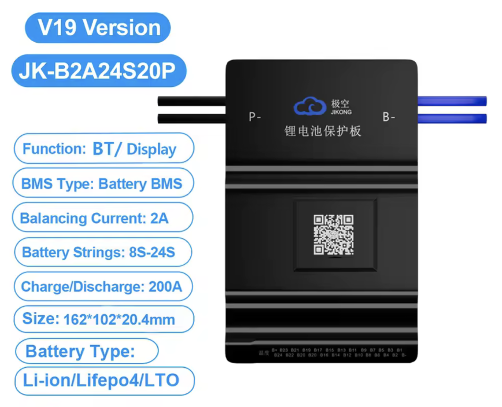
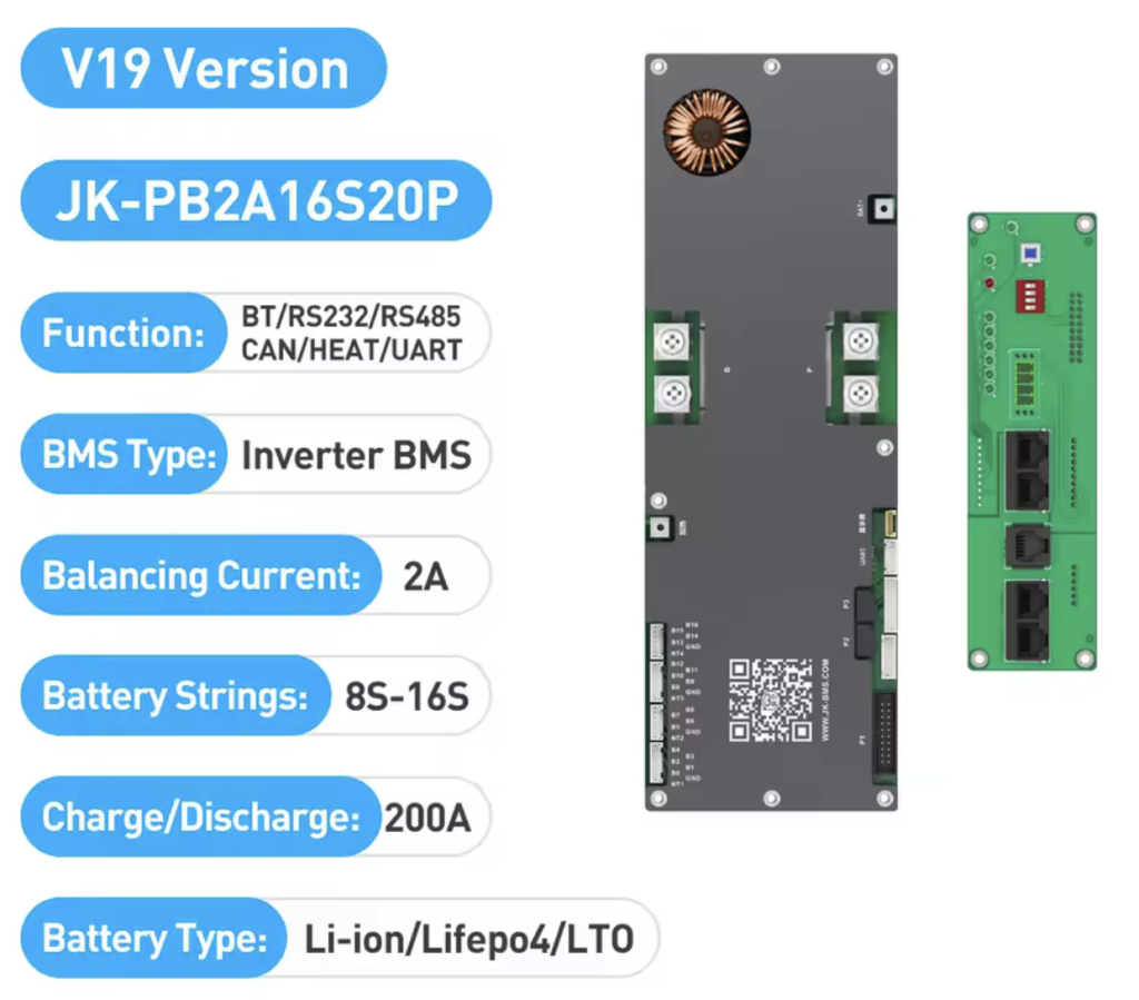
You can decode the JK models as follows. The first letter or two is the series. The first number is how many amps the balancing circuit provides. The next number is the number of cells it supports. The final number is the charge/discharge ability of the inverter in amps. So a PB2A16S20P would have a 2A balancer, handle up to 16 cells (48V) and can charge/discharge 200 amps.
JK series of BMSes – the B series of BMS is good for 12-24V only, the B2 series can do 24-72V and the PB 24-48V. While the B2 series seems to be the most versatile the BMS is actually designed for e-bike and such. There are a number of things that make it different from the B and PB series. I will have an entire blog post about this BMS in the future. I do have 2 of them and they work fine but I would recommend the B series for 12 – 24V or the PB for 24 – 48V. I also recommend you purchase the most BMS you can up front. Rather than get one with a .6A balancer and 100A charge/discharge just get the 2A and 200A or 300A charge/discharge. You can always go in via the Bluetooth application and reduce the balance and/or charge/discharge current.
The PB series is referred to as an inverter BMS. The reason is that it’s often used in 48V batteries that are hooked to solar inverters. While all the JKs have RS485 ports for communication and the B and B2 can be ordered with CAN support, the PB comes with a communication board and RS485/CAN built in. The communication board also allows you to easily daisy chain multiple batteries together with a standard Ethernet cable. Unless you are running a 12V system or have specific space constraints the PB series is the clear choice of BMS to use.
While on the subject of communications pretty much all inverters are able to communicate with batteries. What you need to do is find out what protocol your inverter supports and then go into the BMS and set it for the same. On more advanced systems the inverter can use information from the battery to control charge current, shutdown if voltage is too high or low and many other functions. I’m planning on doing an entire post on how to hook multiple JK BMSes to a Victron system via RS485 and CAN bus in the near future.
Top balancing – when you build your battery it is often said that you should top balance it. What this means is that you should charge each individual cell to 100% before putting them together as a battery. In order to do this you will need a charger capable of producing 3.6V and at least 20 amps. With bigger cells like the 320Ah it can take weeks to get them all top charged. If this is your first battery in your system there is some value in top balancing but I’m not convinced it’s worth the effort. The theory is if you top balance the batteries when you hook it to the BMS you will be at 100% state of charge commonly referred to as SOC. Then you discharge the battery all the way down and then charge it up to 100% again. This calibrates the BMS. My personal experience is that the BMS SOC is often off because of drift and other factors and you really should have a shunt in your system to accurately measure your SOC. In my opinion as long as the cells all have the same voltage to start top balancing is not really necessary.
Cell compression – if you read the forums and watch YouTube videos you will often run across the debate as to if your cells should be compressed or not. The theory is that the batteries, especially in the first few cycles, expand and contract as little gas bubbles are released. By compressing the cells it will prevent the cells from expanding/bulging. Many manufacturers will provide information as to how much compression you should put on their cells. Is compression really necessary, that’s up for debate. Usually a really heated on! I recommend you watch the series of videos on the Off Grid Garage YouTube channel. He goes into depth and builds both batteries with and without compression. I have compressed batteries using a board on each end and 4 threaded rods. My personal opinion is that it’s a lot of effort and expense for not much return. I currently do minimal compression by using packing strapping. Fortunately I have not experienced any issues with cells bulging but your milage may vary.
Tools – there are many tools that make building batteries easier and safer. I’ll go into a bunch of them below.
Multimeters – There are more multimeters than I can cover in the blog but I’ll give you the basics and what you should look for in a meter. For building the battery a meter that does DC voltage and amperage measurement is a necessity. You will also want it to do AC. I recommend that you invest in a decent quality meter like a Klein or Fluke. While you can make do with something less expensive a good quality meter will last you for ever.
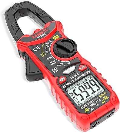
I have a number of meters but when I started getting into solar I found that I needed to measure current pretty often. The best way to do that is to use a clamp meter. Most clamp meters will do everything a regular meter does as well as the ability to measure current. There are a few things to look for in a clamp meter. The first is the ability to measure inrush. When something like a pump is turned on it generates a large power spike for maybe a few miliseconds up to a few seconds. Sometimes it happens so fast that you don’t even see it on the meter. The inrush feature will capture this spike so you can review it. This is a very useful feature to have. Another gotcha is that many clamp meters only capture inrush on AC circuits. It’s handy to have this ability on the DC side as well.
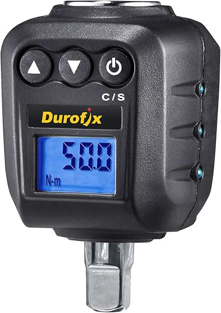
Torque wrenches – when making connections to cells, inverters, etc. almost all have a torque specification by the manufacturer. Having the correct torque is important as it prevents heat and other issues when pulling large amps through your system. A loose connection can cause excessive heat or even worse a failure. As most people already have a socket set and the torque amounts you will need are not very high it may make sense to just get a torque adapter. The adapter is just a small device that goes between the ratchet and socket. They provide a digital readout and beep when the specific torque is reached.
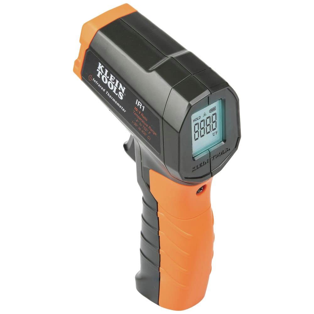
IR Thermometer – While not as necessary as the meter and torque adapter the IR thermometer or a thermal imaging device are very handy to have in your kit. You would use them to look at cells, wiring and anything else related to your battery. They make it easy to find hot spots where something may need to be re-tourqued or maybe even replaced.
That’s about all I have for now. If you have any questions or think of anything else that should be included don’t hesitate to drop me a message.