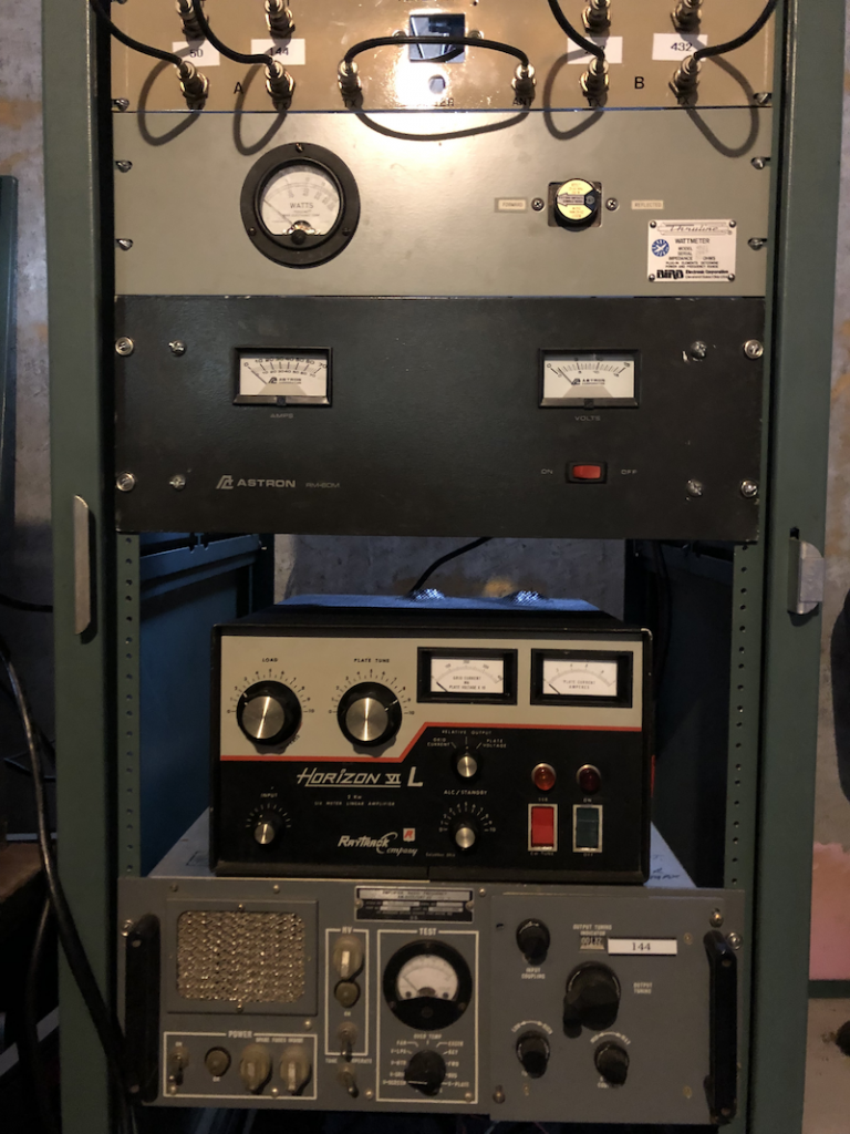
Since I have some antennas back up it’s time to get the old amps back up and running. I have a page about the Raytrack Horizon VI. It’s time to put one up about the AM6155/54. I have 3 of them, one for 144, one for 222 and one as a parts donor. I have (somewhere) the schematics and manual for these amps. As of now there is an issue with the high voltage on the 144 amp but the 222 amp is putting out 325W all day with 5W drive.
Some history about these amps. I want to give credit where due and I believe this info was originally from Steve, KO0U/1, and Harry, W3IIT.
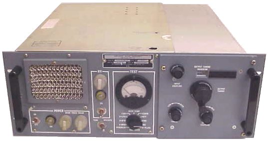
The FAA used the AM-6154 and 6155 amplifiers in the early 1980’s as ground-to-air AM transmitters. The 6154 was designed to cover 118-136 MHz and the 6155 to cover 225-400 MHz. Both models were set to 50 watts output, and amplified an AM exciter.
Both models were rack-mount, 7″ high, 19″ wide, and about 24″ deep; they weigh about 75 pounds and have an internal AC power supply that can be used on 120/240 VAC. They are built so they have a slip-in RF drawer that contains the RF amplifier itself. The main chassis holds the power supplies and a small blower. No T/R switching is included. Because they are intended to be used with the exciter, the amplifier circuitry expects to get some DC control signals from the exciter which have to be simulated by some modifications.
The reason the amplifiers are so interesting to V/UHFers is because they are capable of outputting over 400 watts on 2, 222 or 432 MHz with only a few hours work and almost no extra parts. This is because they use the 8930 tube (or the Amperex equivalent, the DX-393), which is basically a 4CX250R with a 350-watt anode. 50 watts average power of AM is actually four times that power peak; or 200 watts; and these things were designed to do that all day, every day. That’s why they used such a high-power tube for only 50 watts output power.
The RF drawer of either model can be modified for ANY of 2, 222 or 432; but as it comes from the factory, modifications HAVE to be made for any of the three bands. In general, the mods involve redesigning the RF grid circuit to be more efficient and to tune one of the ham bands. The plate circuit in either model can be used on any of the three bands, although use at 400 watts on 432 MHz places a big strain on the stock plate DC choke and plate blocking capacitor, which almost always have to be reworked for serious 432 MHz use. They have apparently proven able to withstand high power on 144 and 222 MHz without modification, although the mods do not hurt.
The power supply chassis is composed of three smaller drop-in chassis, an additional metering PC board, and a 400 Hz 120VAC blower which is powered by a DC-to-AC converter (one of the three drop-in chassis). The high-voltage power supply uses a very compact and lightweight transformer, a dual-section oil-filled filter capacitor, two screen voltage dropping resistors and a string of three zener diodes to regulate the screen voltage. Another drop-in chassis houses the filament transformer which also provides grid bias power and another winding to provide power to the DC-to-AC converter which drives the very small, compact 400 Hz blower (which is able to cool the large tube due to the high speed, 5500 RPM, of the blower).
A front-panel-mounted meter with 12-position switch is also wired to a PC board which contains circuitry that originally monitored the output power and antenna VSWR in addition to the blower current, filament voltage, grid, screen and plate voltage, and plate current. The RF drawer contains a directional coupler and low-pass filter which are almost always removed from the output of the amplifier (and sometimes rewired to the input side) because they don’t handle 400+ watts very well.
More to come as I work on getting these beasts back on the air!