The IC-7300 is a great radio but it only has one RF output. Since my IC-7300 is my primary FT-8 radio, I wanted a way to easily switch between my 6m and 10m antennas. The IC-7300 can provide band data from USB CAT control, the CI-V data interface or as a voltage range via the ACC jack.
My design uses the Arduino to monitor the band voltage from the ACC JACK. A look-up table is used to determine the band in operation and a RF relay is used to switch to the appropriate output.
The ACC jack has a ton of functionality. Take a look at page 18-2 from the user manual for full details. In this case I’m going to pick off 13.8V from pin 8 to power the Arduino, pin 5 for the band data that ranges from 0-8V depending on the band selected and pin 2 for ground.
The Arduino only requires about 250mA to run, include a LCD display. Pin 8 provides up to 1A so this should be fine. The benefit of running off the radio rather than an external source is that the band decoder will shut off if the radio is off.
Pin 5 provides band data ranging from 0V to 8V. This is an issue for the Arduino as the max voltage it can handle is 5V. Therefore we need to use a voltage divider in order to limit the voltage. The voltage divider consists of two resistors connected in series as shown in the diagram below.
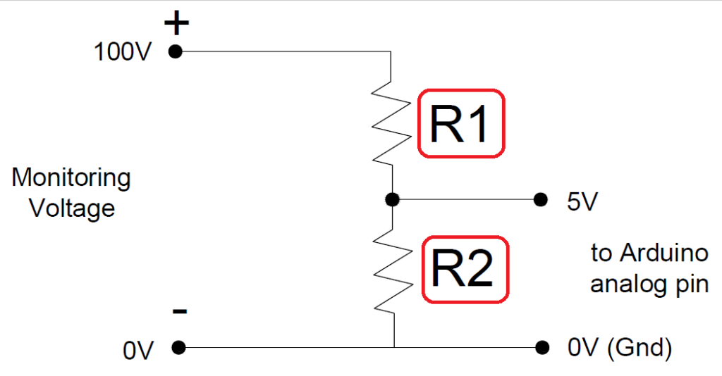
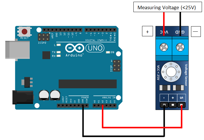
When the voltage is applied across the pair resistor of different resistance, it creates a voltage drop based on each resistor and it can be used as reference value and it is directly proportional to the total voltage value. Higher resistance R1 tends to have larger voltage drop while smaller resistance R2 will have smaller voltage value which is within acceptable range of Arduino. In this case I’m using a 30k ohm resistor for R1 and 7.5k ohm for R2. I found a little premade board for a couple dollars that provides an easy hook up for the Arduino and the IC-7300 with the proper R values.
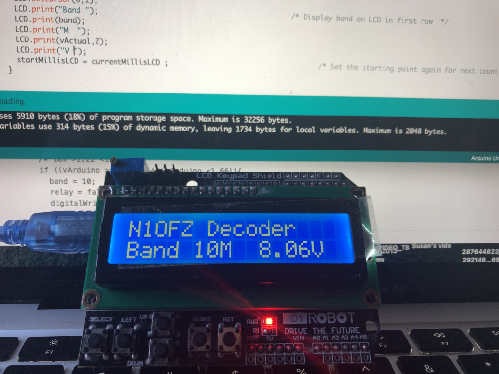
The next part is to put together some code to run on the Arduino. I plan on including a LCD display as well to show what band is in use so I’ll need to add the drivers for the display as well. Below is the code I came up with. It’s based on the voltage meter code that came with the sensor, then I added the code to decode what band is in use and to drive a pin to activate a RF relay. This code could be expanded to switch more than one relay but all I need for now is to switch 6m from HF. Feel free to modify this code to suit your needs.
// Icom Band Decoder - N1OFZ


/* 1 - DC Voltage Measurement */

    int analogInputPin = A2;                    /* This is the analog input pin number in arduino for voltage sensing */
    float vArduino = 0.0;                       /* This is the value voltage sensed by arduino in 0-5 volt */
    float vActual = 0.0;                        /* This is the actual voltage that being measured or monitored */
    float R1 = 30000.0;                         /* This is the resistance (in ohm) of R1 */
    float R2 = 7500.0;                          /* This is the resistance (in ohm) of R2 */
    int rawValueRead= 0;                        /* This is the raw value / analog value detected by Arduino ranges 0 - 1023 */

/* 2 - Relay Output  */

    const int relayPin = 7;                    /* Set pin that controls relay */
    int band = 0;
    bool relay = false;

/* 3 - LCD Display  */

    #include<LiquidCrystal.h>                   /* Load the liquid Crystal Library */
    LiquidCrystal LCD(8,9,4,5,6,7);             /* Creating the LiquidCrystal object named LCD */
    unsigned long startMillisLCD;               /* Start counting time for LCD Display */
    unsigned long currentMillisLCD;             /* Current counting time for LCD Display */
    const unsigned long periodLCD = 1000;       /* Refresh every X seconds (in seconds) in LED Display. Default 1000 = 1 second */

void setup()
{

    /* 1 - DC Voltage Measurement */

    pinMode(analogInputPin, INPUT);             /* Declare analog pin as an input*/
    Serial.begin(9600);                         /* Initialise the Serial Monitor function. The Serial Monitor available at 9600 baud rate*/
    Serial.println("DC VOLTMETER");             /* Describe the function code displayed in Serial Monitor*/

    /* 2 - Relay Output  */

    pinMode(relayPin, OUTPUT);
    pinMode(LED_BUILTIN, OUTPUT);

     /* 3 - LCD Display  */

    LCD.begin(16,2);                            /*Tell Arduino that our LCD has 16 columns and 2 rows*/
    LCD.setCursor(0,0);                         /*Set LCD to upper left corner of display*/
    startMillisLCD = millis();

}


void loop()

{
    /* 1 - DC Voltage Measurement */

    rawValueRead = analogRead(analogInputPin);        /* Read and collect sensor from analog input pin in raw data (0-1023) values */
    vArduino = (rawValueRead * 5.0) / 1024.0;         /* Convert the raw data value into 0 - 5V measurable voltage at analog input pin*/
    vActual = vArduino / (R2/(R1+R2));                /* Calculate the expected monitoring voltage in full voltage*/

    Serial.print("Vdc = ");
    Serial.println(vActual,2);                        /* Print out the result in Serial Monitor, in 2 decimal places*/
    delay(1000);                                      /* Delay or pause for 1.000 seconds*/

   /* 2 - Relay Output  */
    /* 30m >0.00 <0.50 */
    if (vArduino <= 0.50){
      band = 30;
      digitalWrite(LED_BUILTIN, LOW);
      digitalWrite(relayPin, LOW);
      Serial.print("low  ");
    }
    /* 6m >0.50 <1.22 */
    if ((vArduino > 0.50) && (vArduino <1.22)){
      band = 6;
      digitalWrite(LED_BUILTIN, HIGH);
      digitalWrite(relayPin, HIGH);
      Serial.print("high  ");
    }
    /* 10m >1.22 <1.66 */
    if ((vArduino >= 1.22) && (vArduino <1.66)){
      band = 10;
      relay = false;
      digitalWrite(LED_BUILTIN, HIGH);
      digitalWrite(relayPin, HIGH);
      Serial.print("high  ");
    }
    /* 15m >1.66 <2.20 */
    if ((vArduino >= 1.66) && (vArduino <2.20)){
      band = 15;
      digitalWrite(LED_BUILTIN, LOW);
      digitalWrite(relayPin, LOW);
      Serial.print("low  ");
    }
    /* 20m >2.20 <2.75 */
    if ((vArduino >= 2.20) && (vArduino <2.75)){
      band = 20;
      digitalWrite(LED_BUILTIN, LOW);
      digitalWrite(relayPin, LOW);
      Serial.print("low  ");
    }
     /* 40m >2.75 <3.35 */
    if ((vArduino >= 2.75) && (vArduino <3.35)){
      band = 40;
      digitalWrite(LED_BUILTIN, LOW);
      digitalWrite(relayPin, LOW);
      Serial.print("low  ");
    }
     /* 80m >3.35 <4.00 */
    if ((vArduino >= 3.35) && (vArduino <4.00)){
      band = 80;
      digitalWrite(LED_BUILTIN, LOW);
      digitalWrite(relayPin, LOW);
      Serial.print("low  ");
    }
    /* 160m >4.00 <5.00 */
    if (vArduino >= 4.00){
      band = 160;
      digitalWrite(LED_BUILTIN, LOW);
      digitalWrite(relayPin, LOW);
      Serial.print("low  ");
    }

    /* 3 - LCD Display  */

      currentMillisLCD = millis();
      if (currentMillisLCD - startMillisLCD >= periodLCD)
          {
            LCD.setCursor(0,0);                                                    /* Set cursor to first colum 0 and second row 1 */
         //   LCD.print(vActual,2);                                                /* Display voltage value on LCD in first row  */
            LCD.print("N1OFZ Decoder");
            LCD.setCursor(0,1);
            LCD.print("Band ");                                             /* Display band on LCD in first row  */
            LCD.print(band);
            LCD.print("M  ");
            LCD.print(vActual,2);
            LCD.print("V ");
            startMillisLCD = currentMillisLCD ;                                    /* Set the starting point again for next counting time */
          }

}
That’s about it for this project. I’ll going to revise it and add some pictures of this set up in action in the near future.
’73